Engineering
No steel before simulation.
The most expensive mould mistakes happen on screen, not at the machine. Every project therefore starts with a DFM report, a mould concept and a filling simulation; the design phase only ends with your approval.
A-KITA Engineering · Opening simulation of a production mould
Design that explains itself
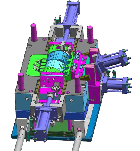
A mould assembly with hydraulic core pulls, animated from a real project: opening sequence, slider travel, ejector stroke. This is how we discuss designs in the review before you approve.
CAD/CAE/CAM at the plant: NX · SolidWorks · Pro/E · AutoCAD
Part analysis & DFM
Mouldability checked systematically, change proposals documented before costs arise.
Mould concept
Cavity count, parting line, gating, demoulding, cooling: the decisions that drive cost.
3D design
Complete assembly with bill of materials, slider and ejector layout, cooling concept.
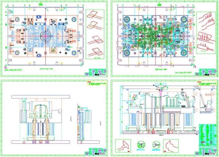
2D & documentation
Manufacturing drawings, electrode planning and the data packages your QA system expects.
What the DFM report checks
Four inspection fields, each with a finding and a recommendation. The document is yours, whether you place the order or not.
Demoulding
Draft angles, undercuts, slider demand. The most common cause of late, expensive changes.
Wall thickness
Steps and material accumulations that create sink marks and warpage, with proposals for rib design.
Gate position
Runner system and gate position, with their effect on weld lines, visible surfaces and rework.
Tolerance chain
Critical dimensions calculated against shrinkage and process variation, plus a measuring concept for sampling.
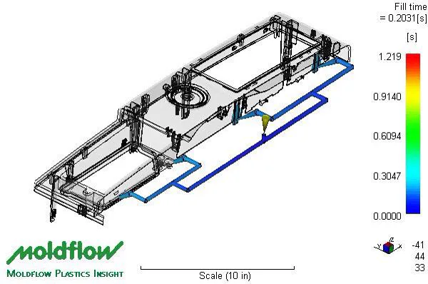
Filling simulation before approval
Filling pattern, weld lines, warpage prediction and cooling, calculated on the designed mould. The rainbow scale is not decoration: it shows where your part runs into problems while they can still be solved in the design.
Data formats we process
Every design engineer's first question, answered up front:
STEP (.stp) · Parasolid (.x_t) · IGES (.igs) · JT · CATPart · SLDPRT · PRT (NX)
PDF · DXF / DWG · Tolerances to ISO 2768 or works standard
Material with grade, annual quantity, tool life, surface specification, target machine.
Your data, your design
In mould projects, confidentiality is a contract clause, not a phrase: NDA before data transfer, exchange via a secured channel, disclosure to the plant only as far as the project requires.
The design is created for your project and handed over with the mould: 3D data, 2D drawings, bill of materials, electrode data. You remain able to act, even without us.
- NDA as standard before data transfer
- Design data in the mould's scope of delivery
- One plant: no scatter across changing suppliers
Send us the part.
The earlier the DFM review sees your design, the cheaper the changes.